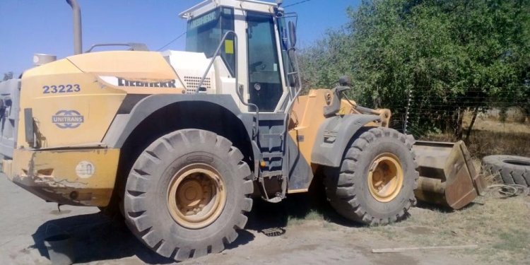
Liebherr Front end Loader
 Model of a Liebherr front loader. Features suspension, 4×4 drive, articulated steering, pneumatically operated arm and bucket, rotating steering wheel, lights and custom stickers.
Datasheet:
Completion date:
Power: electric (8878 battery) / pneumatic (internal motorized compressor)
Dimensions: length 72 studs / width 22 studs / height 31 studs
Weight: 2.220 kg
Suspension: front – none / rear – oscillating axle
Propulsion: 4×4, 2 x PF L motor geared 4.2:1
Motors: 3 x PF L motor, 3 x PF M motor, 1 x micromotor
Originally inspired by the Lego 42030 Volvo Wheel Loader set, this model was designed as its opposite. It was meant to have smooth steering rather than 42030’s jerky Servo motor, and the arm and bucket were to be powered by pneumatics instead of 42030’s linear actuators.
The chassis and insides were, as usual, fully studless, with only thin studless body shell added on top. I have installed both propulsion motors and the battery in the front half of the chassis, making as much room for pneumatics in the rear as possible. This, however, proved futile, as the pneumatic system took enormous amount of space, making the model’s rear end oversized by easily a quarter.
As the amount of available room in the model made me abandon plans for using airtanks and pressure switch, the pneumatic system was eventually limited to two motorized valves and a high-capacity compressor made of four 6L pumps driven directly by a PF L motor. I have initially used Dmac’s solution for self-centering pneumatic valves which would close shut when the motor was off, but I soon found out that the valves don’t open all the way unless they are fixed absolutely steady. As Dmac’s solution essentially stalls PF M motors, the entire torque of the motor was trying to move the valve and I was unable to prevent a slight movement, which in turn prevented valves from opening all the way. Thus the pneumatic system was essentially choking itself, and I was forced to use longer levers to control the valves, solving the problem but losing the self-centering feature. This meant that both valves could not be closed shut remotely – instead, they could be only set to one of their extreme positions. Thus it was not possible to e.g. raise the arm only part of the way and the operate the bucket – operating the bucket would force the arm to go up or down all the way.
Another difficulty arose with the compressor itself. It had to work together with either of the two motors controlling valves, so it could not be coupled with them electrically, and since the motors were being stalled by valves, it could not be coupled mechanically using adder either. In the end I was forced to add separate PF IR receiver just for the compressor and control it separately. This made the remote more complex: it was essentially two remotes, connected bottom-to-bottom, with two levers on the upper one controlling the valves and a single lever on the bottom one activating the compressor. Such a setup made it possible to control all pneumatics remotely using a single hand.
Other than not working exactly the way I intended, the model didn’t look exactly the way I intended. Other than the oversized rear end, there were some inaccuracies resulting from parts shortage. The slopes on the cabin’s sides had wrong angle because I didn’t have white 1×3 slopes, and the sides of the rear bumper were black instead of dark gray because the required dark gray pieces are very rare and would have to be ordered from two separate countries, meaning no less than 2 weeks of waiting. One inaccuracy was intended: the flashing light on cabin’s roof created with a 9V light brick, which I added simply for variety. Finally, my printer was malfunctioning and I was only able to produce black-and-white stickers.


